Solview Command Autocad For Mac
Mainstage 3 Indian Patches Free Download Mainstage three is a superb tune software for use in stay performance, and you may download Mainstage 3 for PC on Windows. It will come up with outstanding revel in as you’re performing on the degree. Here you will find a Collection of Patches for MainStage 3. This patches have been redesigned and eq to cut through the mix for better performance and Worship Sound This patches are compatible with MainStage 3, sound can be imported in to Logic pro X. M-Audio CODE61 FREE MainStage template. Let it be Jesus-G. Ambient Roads is a free electric piano patch for Logic Pro X/MainStage 3. Modwheel controls the volume. A blank MainStage 3 template to start your own! A ES2 default patch for sound design. Ten free worship patches for MainStage 3. Ten free patches from the factory presets that we've used for tutorials. It can be hard to find MainStage patches for worship music in the factory sound library but at Sunday Sounds our goal is to make MainStage fun and easy to use for musicians looking for worship sounds. So, in this download for MainStage 3 you’ll find over 140 free worship patches, all dialed in and ready to play. Mainstage 3 for windows.
A while back I did a post on regular “Vanilla” AutoCAD “Hot Keys” and Aliases that was produced by Autodesk found here. But what about all you AutoCAD Mac users? Below, you'll find an abbreviated list of common commands that can be used on AutoCAD LT. QSAVE / Saves the current drawing. ARC / Creates an arc. ZOOM / Increases or decreases the magnification of the view in the current viewport. WBLOCK / Writes objects or a block to a new drawing file.
21 Jan, 2015By: Bill FaneLearning Curve tutorial: To create 2D views from 3D models quickly, try the ViewBase family of commands.

It was a warm and sunny December morning, just before Christmas. Captain LearnCurve, his gorgeous wife, and their son and daughter-in-law were relaxing in the sun on the deck of the Silver Spirit …
Wait a minute! You live in Vancouver, Canada! How could you be relaxing on the deck of a boat in December?
… about 40 miles offshore from Cairns, Australia, just outside the Great Barrier Reef.
Oh. That would explain it.
Suddenly a shout rang out: 'Divers in the water!' With a series of splashes the Captain and his son stepped overboard, along with the divemaster and four other divers.
That's one fairly big step for Captain LearnCurve ..
Six dives in two days would bring the Captain’s lifetime total to 226. He loves the freedom to move at will in all three dimensions, as opposed to only two when he's on the surface — that’s it! This month’s topic!
Huh?
Generating 2D working drawings from 3D models!
But haven’t you already covered that in two previous columns?
Actually, those two columns hardly covered the half of it. AutoCAD in fact has four basic processes for producing 2D drawings from 3D models.
But previously you said it had three…
More on that later. My first column on this topic covered the FlatShot command, which is the oldest and simplest. It is still the fastest and easiest for producing a quick-and-dirty view but it has too many limitations if you want to get fancy.
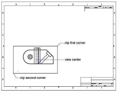
Next came the command sequence using the SolView, SolDraw, and SolProf combination, as covered in my second column of this series. This combination is more powerful and versatile than FlatShot but takes a little more effort, and once again has a few limitations and gnarly bits.
The Power of Positive Procrastination
Time and the Autodesk programmers marched on. In due course they produced the SectionPlane family of commands, which made it much easier to produce 2D drawing and cross-section views.
And AutoCAD 2012 introduced yet another series of 3D-to-2D commands, which make it almost trivially easy to produce 2D drawing and section views from solid models. (So by delaying this column until now, I have cunningly avoided the need to write one about the SectionPlane family.)
In my first article about 3D-to-2D, I bragged that I had created four ortho views and an isometric view in under five minutes. Well, using the ViewBase command I can reproduce that drawing in well under one minute, assuming I have the 3D model to begin with.
I’ll demonstrate, using the same simple part from the earlier article. (You can download it if you want to follow along.)
- Open the drawing file.
- Click on the Layout 1 tab to make it current.
- Delete the existing viewport. (You can eliminate the need for this step in future drawings by deleting it from your template file.)
- Start the ViewBase command. You’ll find it on the Ribbon menu > Layout tab > Create View panel > Base button. A layout tab has to be current for the Layout tab to show. A couple of paragraphs back, I bragged that I could create the 2D drawing views of our sample part in under a minute. Okay, start the clock!
- Having started the ViewBase command, click on From Model Space in the drop-down menu that appears. One Mississippi …
- AutoCAD asks for a view location. Click approximately in the center of the lower-left quadrant of the drawing, then click eXit in the context menu or press Enter. … two Mississippi …
- AutoCAD continues asking for view locations. Click above the first view, then to the right of the first view, then approximately in the center of the upper-right quadrant of the layout, then press Enter.
Xforce keygen 64bits version download. … three Mississippi, four Mississippi … and stop the clock, which shows that it took just a few seconds to produce the figure below. That’s a bit faster than the 16 steps I outlined in the previous article, isn’t it?
With the ViewBase command, it took only four seconds to produce this drawing!
Ah, but the ViewBase command is even trickier. For starters, it assumes that you are going to create at least the three basic orthographic views — front, top, and end —and so it automatically scales the 2D views to suit the page layout sheet size. We’ll have more on this later.
Now we want to add a few dimensions, but there isn’t enough room between the views to fit them in. No problem; simply click anywhere within the top view, then use the little blue square grip to drag it upward a bit. Oops, we forgot to turn Ortho or Polar on — wait a minute, we don’t need to! Orthographic views can only be moved vertically or horizontally, regardless of the Ortho and/or Polar settings! Similarly, moving the base view brings all its ortho children along with it, while isometric views remain independent.
Okay, we’ve added a couple of dimensions to the paper space layout, as shown below. For best results with dimensioning I would suggest using Object mode or EndPoint object snaps to attach the dimensions.
We moved the top view up and added two dimensions.
Free Autodesk software and/or cloud-based services are subject to acceptance of and compliance with the or other applicable terms that accompany such software or cloud-based services.